|
23. Adjustment
of the copying scheme
Adjustment of the copying scheme is carried
out in several steps.
1. Determination of a position of the photoplate
before recording the reflection hologram.
2. Aligning of optical paths of the reference
and signal beams.
3. Adjust the ratio between the reference and
signal beams.
4. Calculation of the hologram exposure time.
Because of importance of adjustment of the ratio
between the reference and signal beams and importance
of determination of the exposure time these
operations are extracted and considered in a
separate lesson.
Determination of a position of the photoplate
for recording the reflection hologram.
By recording the transmission master-hologram
it’s practically impossible to position the
object in a strictly fixed place relative to
the photoplate. A person can involuntarily move
before recording a portrait not to mention domestic
animals, which at all don’t understand the words
"Attention please, I’ll just be taking a photo”.
Even by shooting static compositions their position
can depend on dimensions, content and conception
of a producer. But on the reflection hologram
the image should always be in the same position
– near the centre of the photoplate. Transfer
of the image forward out of the hologram plane
also can’t be quite arbitrary. By a significant
transfer of the image forwards (more than 5
cm) sharpness of the moved forward part of the
image begins to deteriorate even by illumination
of the hologram by a halogen lamp. By a strong
transfer of the image backwards (more than 10
cm) the same effect happens. As optimum the
position of the image near the hologram plane
is considered with location of the most important
parts of the object for example the person’s
eyes by recording a portrait or flowers in a
bouquet on the hologram plane where the image
sharpness is maximum by any source of illumination.
Therefore adjustment of the copying scheme begins
from correction of position of the image restored
by the transmission master-hologram in the plane
of the photoplate.
As we had learned from the previous lesson the
image restored by the transmission master-hologram
is freely “hanging” in the air and even “upside
down” that is it’s turned upside-down in the
vertical plane. This fact significantly embarrasses
tune of the image on the photoplate. For preliminary
adjustment a white screen is inserted into the
frame instead of the photoplate and the image
position is determined with the help of this
screen.
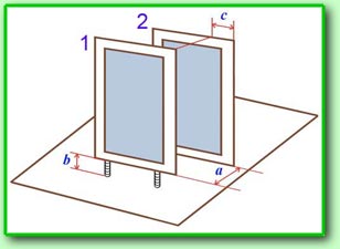 The
frame for the master-hologram is fixed on the
table in a strictly defined position, which
is determined by the path of the restoring beam.
Therefore it’s sufficient to determine three
co-ordinates of position of the frame 1,
see fig., for the photographic plate relative
to the frame 2 for the master-hologram:
a - distance between the frames, b
- the height of position of the frame relative
to the table and c – displacement of
the frames in the plane parallel to the plane
of the master-hologram. If the master-hologram
is copied for the first time it’s necessary
to make several preliminary copies and to remember
the final position of the frame for the photoplate
in order to place it at once into the required
position. For fastening the frame of the photoplate
there is a set of special washers in the complete
set of the copying facility and these washers
allow to lift the frame above the table surface
to the required height with the accuracy of
1 cm and also there is a set of metallic angle
bars with clamps for fixation of position of
the frame relative to the frame for the master-hologram.
The frame for the photoplate and the frame for
the master-hologram should be extremely rigidly
connected with each other because copying is
carried out by the continuous action laser and
the exposure time can reach up to 2 minutes
by the maximum dimensions of the holograms 28x40
cm. Therefore the frames themselves and arrangements
for their fastening are made of metal and the
fastened pair of frames represents a sufficiently
rigid and massive construction. After completion
of setting up the frame for the photoplate preliminary
adjustment of the reference and signal beams
is carried out. The
frame for the master-hologram is fixed on the
table in a strictly defined position, which
is determined by the path of the restoring beam.
Therefore it’s sufficient to determine three
co-ordinates of position of the frame 1,
see fig., for the photographic plate relative
to the frame 2 for the master-hologram:
a - distance between the frames, b
- the height of position of the frame relative
to the table and c – displacement of
the frames in the plane parallel to the plane
of the master-hologram. If the master-hologram
is copied for the first time it’s necessary
to make several preliminary copies and to remember
the final position of the frame for the photoplate
in order to place it at once into the required
position. For fastening the frame of the photoplate
there is a set of special washers in the complete
set of the copying facility and these washers
allow to lift the frame above the table surface
to the required height with the accuracy of
1 cm and also there is a set of metallic angle
bars with clamps for fixation of position of
the frame relative to the frame for the master-hologram.
The frame for the photoplate and the frame for
the master-hologram should be extremely rigidly
connected with each other because copying is
carried out by the continuous action laser and
the exposure time can reach up to 2 minutes
by the maximum dimensions of the holograms 28x40
cm. Therefore the frames themselves and arrangements
for their fastening are made of metal and the
fastened pair of frames represents a sufficiently
rigid and massive construction. After completion
of setting up the frame for the photoplate preliminary
adjustment of the reference and signal beams
is carried out.
 At first the spatial filters
5, see fig. below, are removed and the
not expanded beams are directed to the centre
of the master-hologram and the photoplate by
the mirrors 4. Then the spatial filters
are set at their places and are adjusted as
it was described in the
Lesson 4. Operation
of the spatial filters and quality of illumination
of the master-hologram and the photoplate are
verified with the help of the screens made of
white cardboard. Illumination should be at most
uniform over the whole field with minimum reducing
of illuminance in the angles. At first the spatial filters
5, see fig. below, are removed and the
not expanded beams are directed to the centre
of the master-hologram and the photoplate by
the mirrors 4. Then the spatial filters
are set at their places and are adjusted as
it was described in the
Lesson 4. Operation
of the spatial filters and quality of illumination
of the master-hologram and the photoplate are
verified with the help of the screens made of
white cardboard. Illumination should be at most
uniform over the whole field with minimum reducing
of illuminance in the angles.
Compensation of the difference of path-lengths
of the reference and signal beams.
It’s known that the coherence length of the
He-Ne laser doesn’t exceed 15-20 cm. If additional measures
aren’t taken the difference of path lengths
of the reference and signal beams can approach
to this value. This will bring to the following
result: the contrast of the interference pattern
will decrease and brightness of the holographic
image will diminish significantly. And if the
difference of path-lengths of the reference
and signal beams exceeds the coherence length,
the hologram won’t be recorded at all. Therefore
equalization of the paths of the signal and
reference paths is one of the most important
operations of the adjustment process of the
copying scheme. It’s impossible to do this for
the recording scheme of the Denisyuk holograms
considered in the first paragraph because both
the photoplate and the object are illuminated
by the same beam. For such a scheme division
of the beams into the reference beam and the
signal beam has a rather conditional character.
In essence it’s one and the same beam. Therefore
by recording the Denisyuk holograms there exists
a principal limitation relating to the depth
of the scene being recorded. By the coherence
length of the laser beam of 20 cm the scene
depth can’t exceed 7-8 cm. By the scene depth
of 10 cm the difference of path-lengths of the
reference and signal beams will be equal to
20 cm (double pass of the beam from the photographic
plate to the background and backwards). At that
the contrast of the interference pattern will
fall down to zero and the background won’t be
recorded on the hologram (it will look dark)
even if it was painted by a white colour. There
exists no such problem for the copying scheme
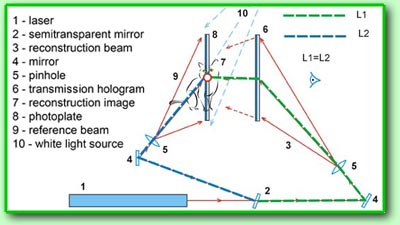
being considered in this paragraph. The signal
and reference beams are formed in the beam splitter
2, see second fig. of this lesson, and
then they separately propagate along their optical
paths marked with the green and blue dotted
lines with the length values of L1 and L2 correspondingly
and afterwards they meet again on the photoplate
8. At that the signal beam has the time
to be transformed passing through the transmission
master-hologram and reaches the photoplate already
in the form of the restored image. For maximum
contrast of the interference pattern the difference
of path-lengths of these beams in the plane
of the photographic plate should be equal to
zero:
L1 = L2
This can be achieved quite simply through changing
positions of the directing mirrors 4
on the paths of the reference and signal beams.
In practice it’s more convenient to displace
position of the mirror located on the path of
the reference beam. The procedure itself for
measurement and compensation of the difference
of path-lengths is rather simple. The elastic
ruler is fastened to the casing of the beam
splitter and the path-lengths of the recording
beams are measured by turns. In case of need
the fixture with the mirror 4 located
on the rail of the optical bench is displaced
to the required side whereupon the difference
of path-lengths of the beams is checked again.
Unfortunately such a procedure leads to displacement
of the reference beam relative to the spatial
filter 5. Therefore when the difference
of path-lengths is finally compensated it’s
necessary to adjust successively the angle position
of the mirror 4 and to tune the spatial
filter 5 of the reference beam in order
that the photoplate be again uniformly illuminated.
-->
|